
Exterior Face, Interior Face, or Centerline
 placed justification plane, or “location line”. The easiest way to establish and use this is in a “flat” view - a plan, elevation, or section. The location line refers to some aspect of the exterior face, interior face, or centerline. In a typical case, the exterior wall location line is set to finished exterior face, say the face of a brick masonry faced wall; The justification for a gyp board stud wall partition is frequently set to face of the supporting stud. the “core” of the wall. In early planning, justifying to the centerline may prove easiest to control, allowing rapid experimentation and adjustment as spaces and rooms divisions are made in resolving program and room configuration.
  |
Portion of a Schematic Design Plan View for a School |
Defining that much may seem over-precise. Why not just “eyeball” (visually estimate the measure) the geometry loosely, at least in the beginning?. But nailing spacing to a precise dimension early actually helps keep design efficient from beginning to end in Revit. At first, materials may not be easy to define and dimensions not known. That doesn’t matter; use a placeholder. A generic 12” or 16” exterior wall works to start. A Generic 5” interior partition will do the job as ideas are forming, and can be swapped out later. Eventually, it may be 4 ⅞” or 5 ¼” , 7 ⅝”, or any of a number of other possibilities. That level of detail can safely come later. The designer can lay strings of working parametric dimensions to quickly adjust and control spacing, keeping geometry simple and understandable with walls alignment to a consistent location line. Wall widths can flex as refinements are made without changing the basic dimension system. Controlled adjustments can be made by simply “nudging” walls with the cursor, or changing the “live” working dimensions. Room area tags can give feedback on resulting areas until a target is reached. The model can be both precise and flexible.
 |
Portion of a Construction Drawing Plan View for a School |
Depending on your priorities as a designer or planner, the most important surface in a room will either be to the face of the underlying structure or to the face of the finish that is applied to it. Architects seem to take sides on this when it comes to dimensioning methods. The first thing placed in construction is the structure, in the case of a partition, the stud. Place it to finish, and you force the framer to do the math on the fly as they subtract intended finish dimension to determine where to mark for the stud location. Easy to make mistakes. On the other hand, when detailing the precise placement of elements in a room, such as a counter or an opening, the designer wants to track the final appearance and fit, not the underlying structure. Thus, the primary dimensions should be to the finish face, instead, right? Revit’s versatility makes this conflict mute. The dimension can be placed to core, while the wall graphic still displays the actual dimensional position of the face layer. The model scales in the true clear dimension to assure design fit while plan dimensions are to the core, the way it is constructed. Design and documentation geometry can finally work together. Different plan and detail views can be created of the same model to meet the needs of the various team players.
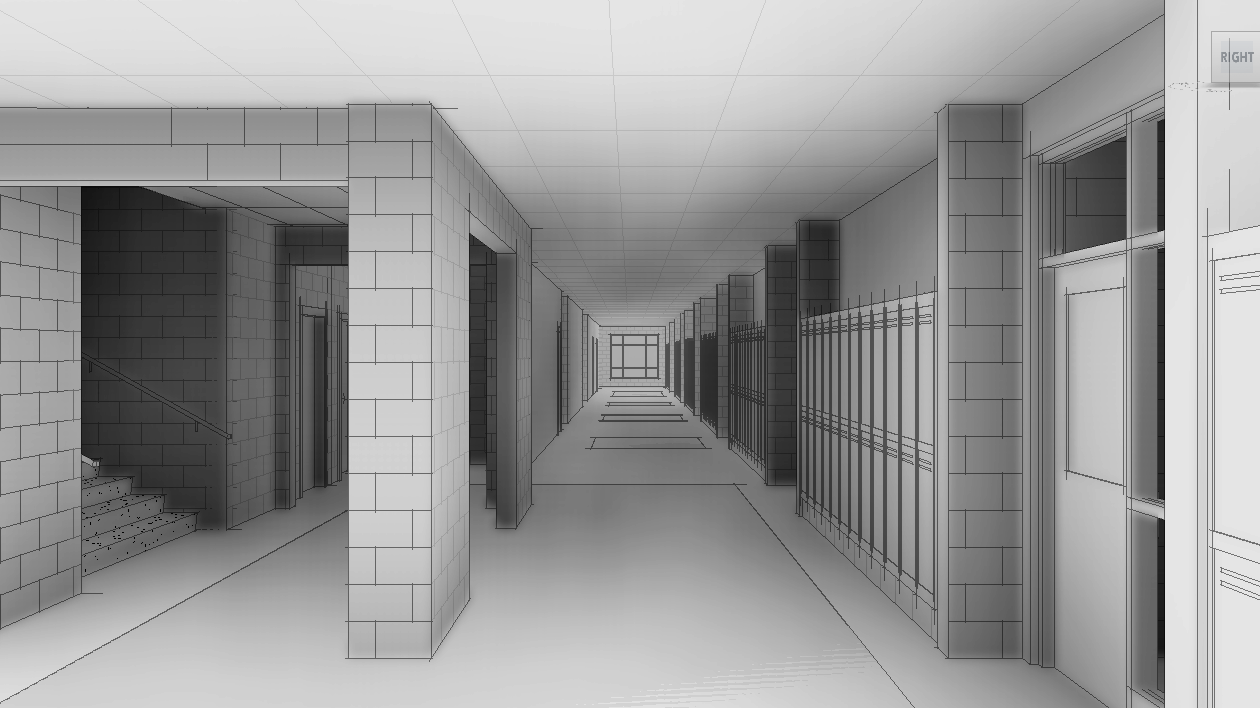 |
Perspective View of School Corridor Design |
The HOW to easily align can be taken for granted in BIM; WHAT we align to can now become the issue. Alignment didn't come so easy in AutoCAD and also forced us to define what line/surface was to be used early on. Revit, and I assume VectorWorks and other platforms, has objects with flexible choices of alignment planes built in, and the ability to seamlessly work from simple to complex, from generic to specific.
ReplyDeleteExterior wall placement is critical in the beginning. It doesn't matter which location (inside, center, outside face) is chosen, but the entire team needs to be aware of it throughout the life of the model. Wall thickness increases from schematic to CD's can affect building size (costs) and potentially site setback encroachments, among other things
ReplyDelete