Translate

Showing posts with label Flexibility. Show all posts

Tuesday, March 3, 2015

Kit of Parts


Architects assemble buildings from individual parts in Revit. Pre-set elements are part of templates and libraries for easy access. Any building starts from a kit of parts, just like the furniture from IKEA. A ready library of walls, floors, roofs, windows, doors, stairs, components, annotations, and formats can be customized to whatever you want for the design and documentation of architecture in the Revit Building Information Model environment. You can set it up as you please.

Best Practice

Is there a best way to approach to creating a uniform set of building blocks in Revit? Standards sometimes exist for standards’ sake and are not worth having unless they make things better. A good Revit standard keeps work clean and understandable, with fewer unnecessary steps or distracting choices; no need to “reinvent the wheel” every time. On the other hand, over-defined standards can become overwhelming, reducing speed and flexibility. The value of setting elements up before hand goes away if the Revit user is tempted to abandon the system and make what they need ad-hoc.

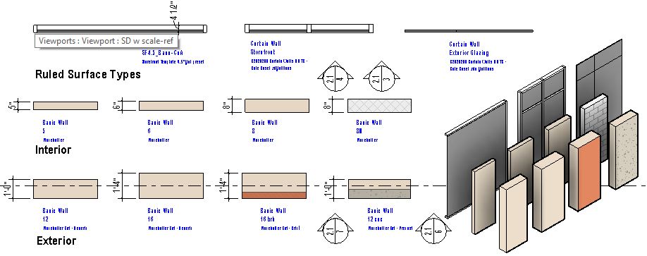
Building the Library from Generic to Realistic

A kit of parts that works in Revit starts with generic components and extends to the more complex. No need to force detailed decisions early. Provide a basic spectrum of choices systematically named so the designer can find them. Show only to the level of detail that is needed to communicate clearly, which is no different that in the days of hand drafting. Just because we can show high level of detail in Revit doesn't mean we should. Don’t weigh the process down.

Look it Up

One of the most important aspects of a good library is to clearly codify the choices. A graduated series of standard components can be given short, logical, findable names. Keep the library small, containing just the parts that serve as “seeds” for duplicating to similar types parametricly.
Human memory is limited, but we can always look it up, or make it as we need it according to a system.  
Standards should extend to the text, tagging and formatting of the model in all phases, from schematic through construction documents. Good standards streamline and help us visualize and communicate the work, The same model serves as the basis for clear diagrams and stunning presentations as well as highly technical documentation, with format styles already built in. In Revit, it is best to set it all up right from the start, with an effective kit of parts.


Wednesday, February 11, 2015

The Justification for Alignment

Architects love to align things,... professionally.   Original typesetting involved “justifing” text to “make it perfect” by aligning left and right margins, now anything that can be aligned uses this sense of the word.  Architects take a keen interest in this subject and Revit parametric models make it easy.  A prime example is how architects work with walls.  We assign a plane of alignment to a Revit object that helps quickly, precisely control how they are placed as we compose in plan.  (See the previous post, Dimensions - the Nominal,  the Actual, and the Usable,  for a “prequel” on Revit dimensioning).


Exterior Face, Interior Face, or Centerline

A building, unlike justified letter type, is in three dimensions.  Walls in Revit have a defined, flexibly 

placed justification plane, or “location line”. The easiest way to establish and use this is in a “flat” view - a plan, elevation, or section.  The location line refers to some aspect of the exterior face, interior face, or centerline.  In a typical case, the exterior wall location line is set to finished exterior face, say the  face of a brick masonry faced wall; The justification for a gyp board stud wall partition is frequently set to face of the supporting stud. the “core” of the wall.  In early planning, justifying to the centerline may prove easiest to control, allowing rapid experimentation and adjustment as spaces and rooms divisions are made in resolving program and room configuration.

Eyeballing vs. Nailing It in Schematic Design

Portion of a Schematic Design Plan View for a School
Defining that much may seem over-precise. Why not just “eyeball” (visually estimate the measure) the geometry loosely, at least in the beginning?. But nailing spacing to a precise dimension early actually helps keep design efficient from beginning to end in Revit.  At first, materials may not be easy to define and dimensions not known.  That doesn’t matter; use a placeholder.  A generic 12” or 16” exterior wall works to start.  A Generic 5” interior partition will do the job as ideas are forming, and can be swapped out later. Eventually, it may be 4 ⅞” or 5 ¼” , 7 ⅝”, or any of a number of other possibilities.  That level of detail can safely come later.  The designer can lay strings of working parametric dimensions to quickly adjust and control spacing, keeping geometry simple and understandable with walls alignment to a consistent location line.  Wall widths can flex as refinements are made without changing the basic dimension system.  Controlled adjustments can be made by simply “nudging” walls with the cursor, or changing the “live” working dimensions.  Room area tags can give feedback on resulting areas until a target is reached.  The model can be both precise and flexible.


Portion of a Construction Drawing Plan View for a School
Declaring Peace in the Dimensional War
Depending on your priorities as a designer or planner, the most important surface in a room will either be to the face of the underlying structure or to the face of the finish that is applied to it.  Architects seem to take sides on this when it comes to dimensioning methods.  The first thing placed in construction is the structure, in the case of a partition, the stud.  Place it to finish, and you force the framer to do the math on the fly as they subtract intended finish dimension to determine where to mark for the stud location.  Easy to make mistakes.  On the other hand, when detailing the precise placement of elements in a room, such as a counter or an opening, the designer wants to track the final appearance and fit, not the underlying structure.  Thus, the primary dimensions should be to the finish face, instead, right?  Revit’s versatility makes this conflict mute. The dimension can be placed to core, while the wall graphic still displays the actual dimensional position of the face layer.  The model scales in the true clear dimension to assure design fit while plan dimensions are to the core, the way it is constructed.  Design and documentation geometry can finally work together. Different plan and detail views can be created of the same model to meet the needs of the various team players.   

Perspective View of School Corridor Design
Revit enables collaboration and integration.  No need for the thinking of schematic design, interior design, and construction documentation thinking to stay isolated in silos.  One of the most important outcomes of using a model interactively like this is to allow us to form and describe the architecture with an eye to the final outcome, coherent and useful space.  A peaceful outcome.


Thursday, November 20, 2014

The BIM Placeholder - Hold that Thought!


Architecture is broad in conception, but also intensely detailed.  Two distinct forms of thinking are needed to get a design off the ground and a building into the ground.  To resolve a design, the architect must branch out and explore, but also refine and nail down. Architects have a long tradition of how this process works: loose sketching of options, expressing  and presenting proposals for debate, for decisions.  Finally, design complete, there is a hand-off, and the process of committing to hard lines and exact descriptions begin.  Narrowing down is relentless, so that the many interconnected details can be addressed. Proceed one step at a time, and, above all NO CHANGES to the design. This split promotes two cultures in any practice: the dreamers and the realists, each working in a separate room.

The computer helped relax the thinking process in many fields. A writer of old would write by hand or peck on a typewriter, then wrinkle the paper into a ball, and start again. Editors with edits and printers with proofs each came in strict succession. A somewhat different workflow than now when using MS Word. We have become accustomed to an interactive process.  

Enter the Building Information Model. Architects compose and link a network of objects to describe the design, giving the building coherent form, proportion,enclosure, structure, functions, and so on. The schematic design serves as the overarching outline of placeholders for a large amount of detailed information that will eventually be resolved.


Schematic Design
Peter Cholakis, in his Building Information Management blog describes it:  "Some information is more appropriately located in the ‘geometrical’ part of the BIM object while other information is more suited to the ‘properties’ part, such as the specification. The specification is part of the project BIM, and objects live in the specification. In traditional documentation we would ‘say it once, and in the right place’, however with BIM, we want to ‘author it once, and in the right place, to be able to report it many times’. ...Take the analogy of a BIM object representing a simple cavity wall. The object will tell us the width of the brickwork and height of the wall. However at a certain point in the project cycle it is the written word that is needed to take us to a deeper level of information. It is within a textual context that we describe the length, height and depth of the brick. It is words that are used to describe the mortar joint and wall ties."

Construction Documents
Elements of the design are necessarily generic and simplified to start, giving power to organize  the project.  Elements are stripped down to their basic form as placeholders for extensive, interconnected detail to come. This is important in many fields.  A satellite engineer from Johns Hopkins Applied Physics Lab I know uses placeholders,  “At the beginning of a project, the exact nature of the content may not matter, or even exist yet. Or maybe having actual content would be too distracting from the problem at hand.”

Graphic and web designers have been know to use lorem ipsum, and even placekittens to hold the place of eventual text and images to help bring focus to the task of structuring the page or site.
Lorem Ipsum placeholder text
In the old school, the “design” has to be finished before before “detailing” begins. (Draw it Once!) Now the evolving design has a living backbone to support  a combined team effort. Concept and detail stay linked.  No risk of ever having to collectively crumple up the paper and start all over again. The building information model outline can adjusts, continuing to hold a hierarchy of details as they develop.

That is my vision for BIM in the workplace.  What is your experience?  Does BIM actually foster flexibility in design, increased collaboration, more integrated detail, or is the verdict still out?  Looking forward to seeing a dialogue in "Comments".