Translate

Showing posts with label Concept. Show all posts

Wednesday, February 11, 2015

The Justification for Alignment

Architects love to align things,... professionally.   Original typesetting involved “justifing” text to “make it perfect” by aligning left and right margins, now anything that can be aligned uses this sense of the word.  Architects take a keen interest in this subject and Revit parametric models make it easy.  A prime example is how architects work with walls.  We assign a plane of alignment to a Revit object that helps quickly, precisely control how they are placed as we compose in plan.  (See the previous post, Dimensions - the Nominal,  the Actual, and the Usable,  for a “prequel” on Revit dimensioning).


Exterior Face, Interior Face, or Centerline
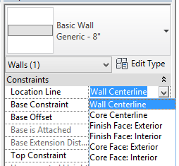
A building, unlike justified letter type, is in three dimensions.  Walls in Revit have a defined, flexibly 

placed justification plane, or “location line”. The easiest way to establish and use this is in a “flat” view - a plan, elevation, or section.  The location line refers to some aspect of the exterior face, interior face, or centerline.  In a typical case, the exterior wall location line is set to finished exterior face, say the  face of a brick masonry faced wall; The justification for a gyp board stud wall partition is frequently set to face of the supporting stud. the “core” of the wall.  In early planning, justifying to the centerline may prove easiest to control, allowing rapid experimentation and adjustment as spaces and rooms divisions are made in resolving program and room configuration.

Eyeballing vs. Nailing It in Schematic Design

Portion of a Schematic Design Plan View for a School
Defining that much may seem over-precise. Why not just “eyeball” (visually estimate the measure) the geometry loosely, at least in the beginning?. But nailing spacing to a precise dimension early actually helps keep design efficient from beginning to end in Revit.  At first, materials may not be easy to define and dimensions not known.  That doesn’t matter; use a placeholder.  A generic 12” or 16” exterior wall works to start.  A Generic 5” interior partition will do the job as ideas are forming, and can be swapped out later. Eventually, it may be 4 ⅞” or 5 ¼” , 7 ⅝”, or any of a number of other possibilities.  That level of detail can safely come later.  The designer can lay strings of working parametric dimensions to quickly adjust and control spacing, keeping geometry simple and understandable with walls alignment to a consistent location line.  Wall widths can flex as refinements are made without changing the basic dimension system.  Controlled adjustments can be made by simply “nudging” walls with the cursor, or changing the “live” working dimensions.  Room area tags can give feedback on resulting areas until a target is reached.  The model can be both precise and flexible.


Portion of a Construction Drawing Plan View for a School
Declaring Peace in the Dimensional War
Depending on your priorities as a designer or planner, the most important surface in a room will either be to the face of the underlying structure or to the face of the finish that is applied to it.  Architects seem to take sides on this when it comes to dimensioning methods.  The first thing placed in construction is the structure, in the case of a partition, the stud.  Place it to finish, and you force the framer to do the math on the fly as they subtract intended finish dimension to determine where to mark for the stud location.  Easy to make mistakes.  On the other hand, when detailing the precise placement of elements in a room, such as a counter or an opening, the designer wants to track the final appearance and fit, not the underlying structure.  Thus, the primary dimensions should be to the finish face, instead, right?  Revit’s versatility makes this conflict mute. The dimension can be placed to core, while the wall graphic still displays the actual dimensional position of the face layer.  The model scales in the true clear dimension to assure design fit while plan dimensions are to the core, the way it is constructed.  Design and documentation geometry can finally work together. Different plan and detail views can be created of the same model to meet the needs of the various team players.   
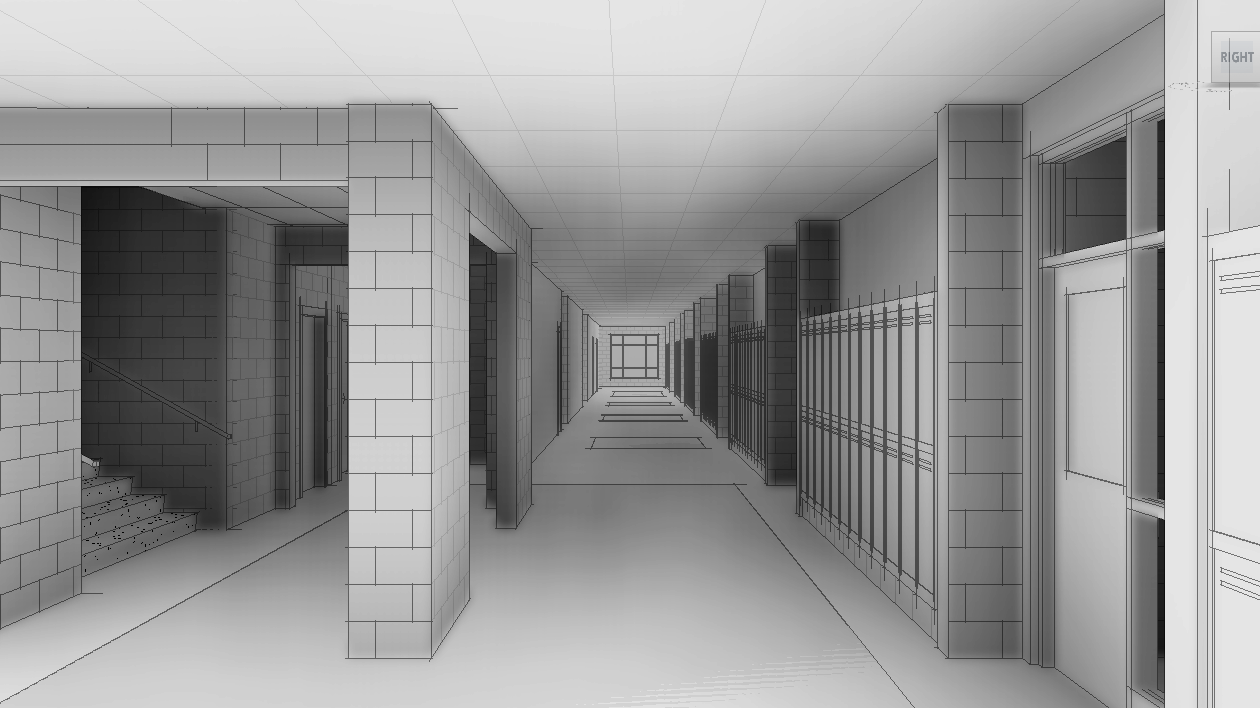
Perspective View of School Corridor Design
Revit enables collaboration and integration.  No need for the thinking of schematic design, interior design, and construction documentation thinking to stay isolated in silos.  One of the most important outcomes of using a model interactively like this is to allow us to form and describe the architecture with an eye to the final outcome, coherent and useful space.  A peaceful outcome.


Tuesday, December 2, 2014

The Revit Concept - Past and Future

LeCorbusier's Modulor
Revit is conceptual; it is a software tool for virtual modeling in the practice of architecture that, for me, is at once a new paradigm and a revival of an older way of thinking.  The new tool, variously called "Building Information Modeling," (BIM), or "Virtual Design and Construction" (VDC), has been a welcome change in the field.

The Beginning

When I studied architecture in the late 1970’s at Cornell, I learned from the work of the modern masters: LeCorbusier, Mies, Wright, Aalto, Kahn, and some newer folks: Meyer, Stirling, Rossi, and others. Thanks to professors Colin Rowe and Mathias Ungers, we were also pointed back to the great precedents before the modern era, and pointed forward to the larger world around us. Design started with criteria for the program and the context. A parti, the big idea, was diagrammed and tested. Architectural elements, including walls, floors, roofs, and openings, built on the parti. These were the elements of architecture , with the designer sketching, drafting, and rendering, and, at times, building a physical model to work out the idea.

The CAD Era

Shortly after I went into practice in the 1980's, the digital age brought a new, helpful, but demanding tool into architecture: Enter Computer Aided Design and Drafting (but with special emphasis on “drafting”). Not purpose built for Architects, CAD had its beginnings in Aerospace. Any discipline could use it for any kind of delineation (I remember my surprise when I saw "Ångström" as one of the choices for setting the units, not just feet or meters). A new vocabulary came to dominate our work: Point, Line, Layer, Xref. The tool brought incredible accuracy, but its narrow focus often distracted from forming ideas and buildings.

CAD came to dominate how we developed designs and produced construction documents, taking the place of the team of hand drafters of past eras. Most simply used it for more efficient 2D drafting. AutoCAD did offer awkward 3D tools within its software packages, but these would go largely untapped. Outside applications crept in, like Sketchup and 3DMax, out of sheer necessity to see the building more fully. Adding and scheduling elements of the building remained a "one item at a time" process, with some assistance from the copy command and spreadsheet software. The computer had automated and integrated the working process in many fields in the 1980's and '90's, but not in architecture.

Back to the Beginning

By 2000, advances in computing started to offer a practical road back to the original focus of architectural design, and leave traditional drafting behind. Architects could begin to work directly in an integrated environment of the virtual building model that completely linked information, and creating a wide variety of 2D and 3D views automatically. When I became aware of Revit as one of these new accessible BIM packages 10 years ago, I jumped in. Away with machine drafting to trace out buildings in in a complicated sequence of glowing vectors and color coded layers. I missed architecture.  

Since then, I have been immersed in the virtual building information model. I am back to the conceptual basic building blocks of wall, column, floor, and roof. I now mold and describe forms, space, and functions as I learned in school. Endless cross references from drawing to drawing update themselves as details shift and change. I am writing this blog, Revit Reflections, to explore ways Revit has energized my work as an Architect, and, in many ways, brought me back to my roots.


Monday, November 3, 2014

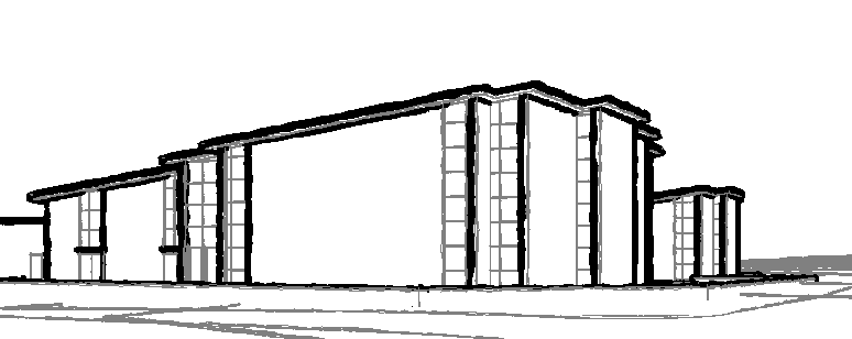
Magic in the Sketched Line

In its latest retro feature, Revit Building Information Modeling software can now show a view of a design as if it was sketched by hand.  I had been long awaiting this.  At least twenty years ago, a software called Squiggle cleverly offered to translate the cold hard lines of a design in AutoCAD to sketch form, warming the audience to a more humane presentation of computer aided drafting. What is it about the appearance of less certain lines and more ambiguous images that invite us in,  where mathematically perfect lines and images often repel?

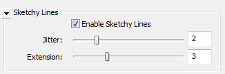
sketchsettings2.pngA sketch is by its very nature spontaneous and rapid.  The thought is being born, not dryly reported.  The irony of a computer simulated sketch is that its seeming relaxed random line style is strictly proscribed. In Revit’s version the parameters are “jitter”, how the sketcher waves the line from straight, and “extension”, how much the sketcher overshoots lines at intersections.  The exact geometry has to come first, not the other way round as in the old school.


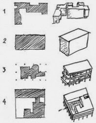
Long before computers, the original intent of a hand sketch was to quickly, flexibly translate thoughts to paper, the detail not yet completely known. A sketch was an informal study that allowed rapid iteration of ideas that were not predetermined: a stream of consciousness.  The sketch invited participation. You could see what you wanted in its more ambiguous play of lines.  Da Vinci’s flying machine is credible without quibbling about details. LeCorbusier's classic building typology is appealing and believable, abstracted to basic concepts.

Revit’s choice of the word “Sketchy” is perhaps unfortunate, since sketchy thinking doesn't share the trust that the sketch itself does. A sketch can hide things: flaws that would doom the feasibility of a design, or perhaps bring unmerited appeal through “eyewash,” like pretty composition or shading; a cloud or tree in the right place.  The architect’s “napkin sketch” is famous: the miraculous birth of the design. More often, though, this clarity comes as the design evolves and is refined.  Often the great napkin sketch, the parti of the building, is hand traced  over the final design drawings, much as Revit abstracts the sketch from a set of hard lines.

I tried my hand at input of concept using Revit’s new “sketchy” interface myself, rapidly outlining a series of walls and roofs to form trial concepts for a new building.  It was freeing, but was I fooling myself?. Even as I was able to stay in scale and form spaces to the needed sizes, as is only possible with some level of automation, I did experience more flexibility, less focus on distracting detail.  Hand sketch advocates on the team brightened up and felt more relaxed in offering ideas. 
The design came together. Magic? 


Sunday, October 19, 2014

Crunching Areas in a Model

Architects are frequently hounded by the task of area tracking as they practice in the real functional and economic world.  Early in design, the  person drawing the design establishes, quantifies, parses, analyses, sorts, and re-sorts areas describing each function needed in a building. How to areas fit to opportunities for form?  How can and should areas be grouped, consolidated, separated?  And, of course, the bottom line, what area fits the budget? Building Information modeling is the ultimate tool to make this tracking work.

In past, drawings in the schematic design phase were famous for fudging the area numbers.  How else could the Architect draw up a guiding strategy as fast as the thought process, and arrive at the basic outline of the building plan? Design ideas come quickly, accurate accounting less so. The more complete the numbers, the more likely, with so much time invested in computation, that the plan becomes established and inflexible.  Hand sketched schematics require setting a scale to plan, and punching length and width into calculator. CAD improved the situation somewhat, with the ability to surround areas with a polyline that listed area. Facilities management programs can attach these areas to reports, but require extra steps not integrated into the design process as a whole.

Number crunching in Revit is straightforward, as shown in the Revit Wiki and the Revit Zone websites, citing two sources.  A building information model, as it is created in Revit, is at once a geometric, graphic and numerical data base.  On the plan level, a room is reported graphically bounded by walls or area separation lines.  This room can also be reported by any other of its properties, including its area, assigned department, occupancy, function, or anything else.  These properties can be sorted and reported in tables (like an excel spreadsheet), or in color coded plans alike.

Net Areas
The multi-clinic medical center shown is one example of design area tracking in Revit. When rooms are sorted by contribution to net area, the Architect can verify alignment to the user's program needs as a whole.  Using a ratio with gross area, the architect can test the efficiency of the proposed plan layout.  We can flexibly nudge walls, add, subtract, consolidate, rearrange, and test the patterns:  numerical feedback is immediate.  The graphics give us a clear picture of what is being accomplished, and may point out new directions.

Departments

Using the clinic center as an example, other properties can be assigned and tracked.  The designer as well as the building end user will want to see where individual clinics and their supporting services are proposed. The visual report in plan is immediate and convincing.  Drilling down yet further, we can see how sub-functions relate: private or public, served or served or serving.  Exam rooms and individual offices are the basic building blocks of this particular building program.  Lobbies, corridors, labs, toilets, and other functions serve these in the larger hierarchy of spaces.  These properties appear in tabulated, sort-able lists, and also can be tested and visualized with color coding in plan.
Functions

Many see the power of modeling for three dimensions early in the design process.  The model in Revit certainly provides this, as do many other software modeling packages like Sketch-up and 3dMax. Less tapped is the modeling of area early in planning,  This requires a true integrated building information modeler like Revit.